Distributed Circuit#3: Driven Lossless Infinite Transmission Line with Source Impedance

When we are driving a distributed circuit, a transmission line in this case, we usually do not drive it directly with an ideal voltage source, rather we usually drive it with a voltage source which has non-zero source impedance, denoted by \(Z_{s}\) in the Figure 1 above. Sometimes we also often hear the term "power source" when driving a distributed circuit. What does this mean? Circuit-wise, a power source is always equivalent to voltage source with source impedance (due to Thevnin's theorem). The difference is that voltage swings in power sources are dependent on its load and how they are matched. The power value in "power sources" denotes the overall transferred power at the load when source impedance is matched to load impedance ( usually they are matched to 50ohm, i.e. \(Z_{s}=Z_{0}=50\Omega\) ). Under 50ohm matched source and load impedance consideration, a harmonic AC 10dBm=10mW power source will exhibit \(E_{x=0}(t)=0.707 \space Vrms\) at the input of the load, which means that the value of the ideal voltage source before the source impedance is \(E(t)=1.414 \space Vrms\).
On another note, we should also remember that although both represent impedances, there is clear distinction between the physical meaning of \(Z_{s}\) and \(Z_{0}\). \(Z_{s}\) represent lumped impedance element at source side which is a real electrical component. \(Z_{0}\) on the other hand represent characteristic impedance of transmission line which is a physical property of the medium and does not represent any real electrical component. \(Z_{0}\) is called "impedance" because it describes how voltage and current waveform are related to each other in the medium.
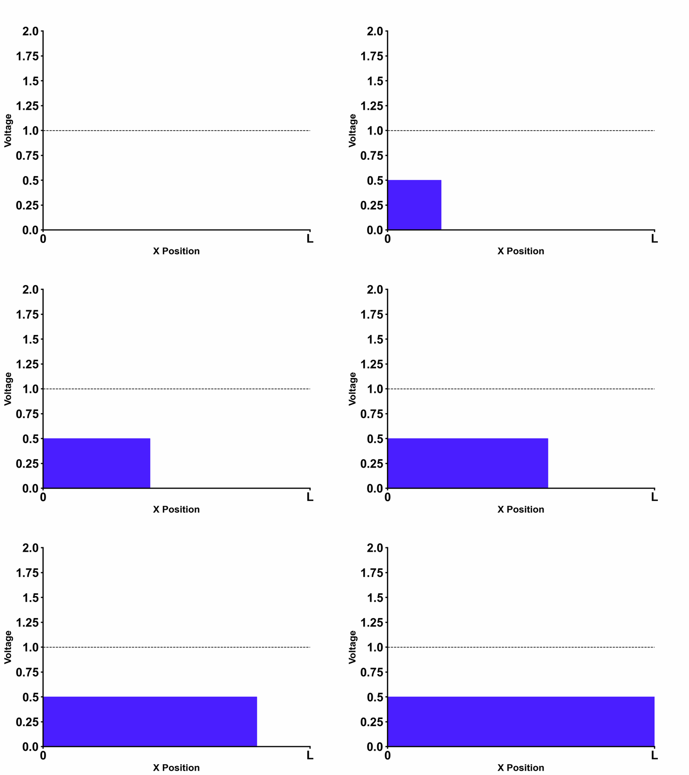
Going back to our example in figure 1, we can see that the following boundary conditions apply to our example:
- \[V_{-}=0 \space (convergence \space at \space x=\infty)\]
- \[E_{(s)}-V_{(0,s)}=I_{(0,s)}Z_{s} \space \rightarrow \space E_{(s)}-V_{+}=\frac{V_{+}}{Z_{0}}Z_{s} \space (ohm's \space law \space at \space x=0)\]

It should be noted that adding source impedance will not only result in voltage divider operation as the figure shows. Depending on the source impedance value, it may also introduce reflections from the source-side which will be explored in the next chapters.