We often overcomplicate how a transmission line would respond to a certain input because it is often hard to imagine transmission line as your everyday linear electrical component. However, transmission line is in fact a linear electrical component. It has to be, since we model it that way - using linear lumped elements -. From this fact alone, we know that finding how a transmission line responds to a certain input should not be a complicated task, although it may look that way when we only consider the time domain solution of the telegrapher's equation. This overcomplication all goes out the window when we look at the solution in Laplace domain. In Laplace domain, every LTI system response can be described using the concept of "transfer function". Transmission line, as an LTI system is not an exception to this rule. Hence, we can always express the response of a transmission line with regards to a certain input as follows: \[V_{(x,s)}=T_{(x,s)} \times E_{(s)}\] Here, \(V_{(x,s)}\) is the transmission line response at location \(x\), \(T_{(x,s)}\) is the "transfer function" of the transmission line for location \(x\), and \(E_{(s)}\) is the input.
On another note, when talking about transmission line, we often assume lossless transmission line i.e. \(R=0 , G=0\). Under this assumption, the term \(\gamma_{(s)}\) becomes: \[\gamma_{(s)}=\sqrt{(G+sC)(R+sL)}=s\sqrt{LC}\] Here, \(\sqrt{LC}\) represents propagation delay in the transmission line medium, which means that the propagation speed can be expressed as \(v_{p}=\frac{1}{\sqrt{LC}}\). Furthermore, lossless assumption also implies that \(Z_{0}=real \space constant\) , which simplifies a lot of calculation.
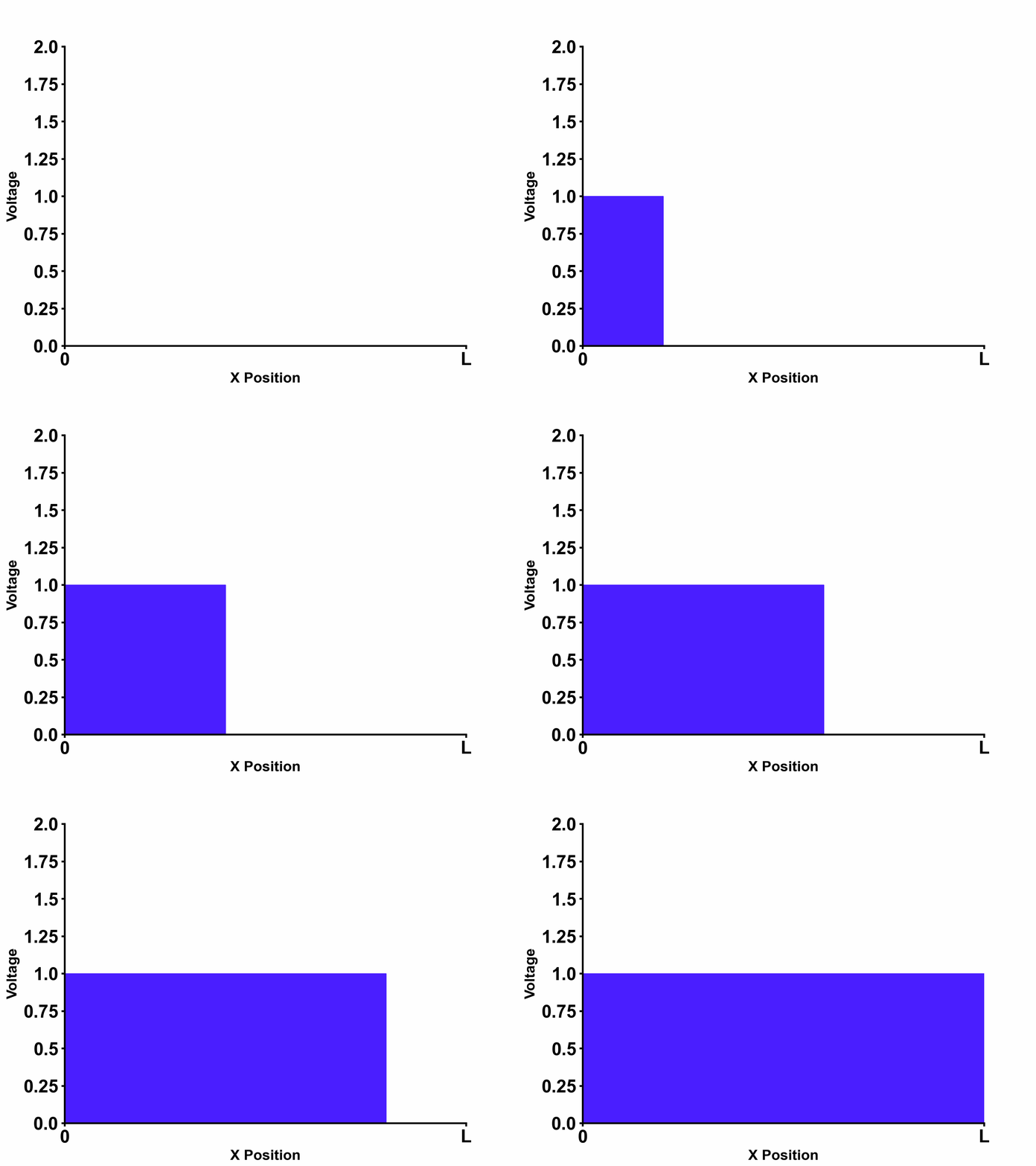
Going back to our example in figure 1, we can see that the following boundary conditions apply to our example: \[V_{-}=0 \space (convergence \space at \space x=\infty)\] \[V_{(0,s)}=V_{+}e^{\gamma_{(s)}0}=E_{(s)} \space \rightarrow \space V_{+}=E_{(s)} \space (boundary \space at \space x=0)\] Applying both boundary conditions, we can obtain the final solution in laplace domain as follows which indeed separates into "input" and "transfer function" terms as expected: \[V_{(x,s)}=E_{(s)} \times e^{-s\sqrt{LC}x} \] \[I_{(x,s)}=E_{(s)} \times \frac{1}{Z_{0}}e^{-s\sqrt{LC}x} \] Multiplying by \(e^{-s\sqrt{LC}x}\) in laplace domain is the same as adding \(\sqrt{LC}x\) delay in time domain, hence doing reverse laplace transform on the equations above will give us time domain solution as follows: \[V_{(x,t)}=E_{(t-\sqrt{LC}x)}\] \[I_{(x,t)}=E_{(t-\sqrt{LC}x)} \times \frac{1}{Z_{0}} \] From this result, we can see that the voltage at location \(x\) is delayed due to limited propagation speed in the transmission line. Much clearer visualization of this phenomenon is shown in Figure 2 below. In the picture, step input voltage \(E(t)=u(t)\) is applied at \(x=0\).
