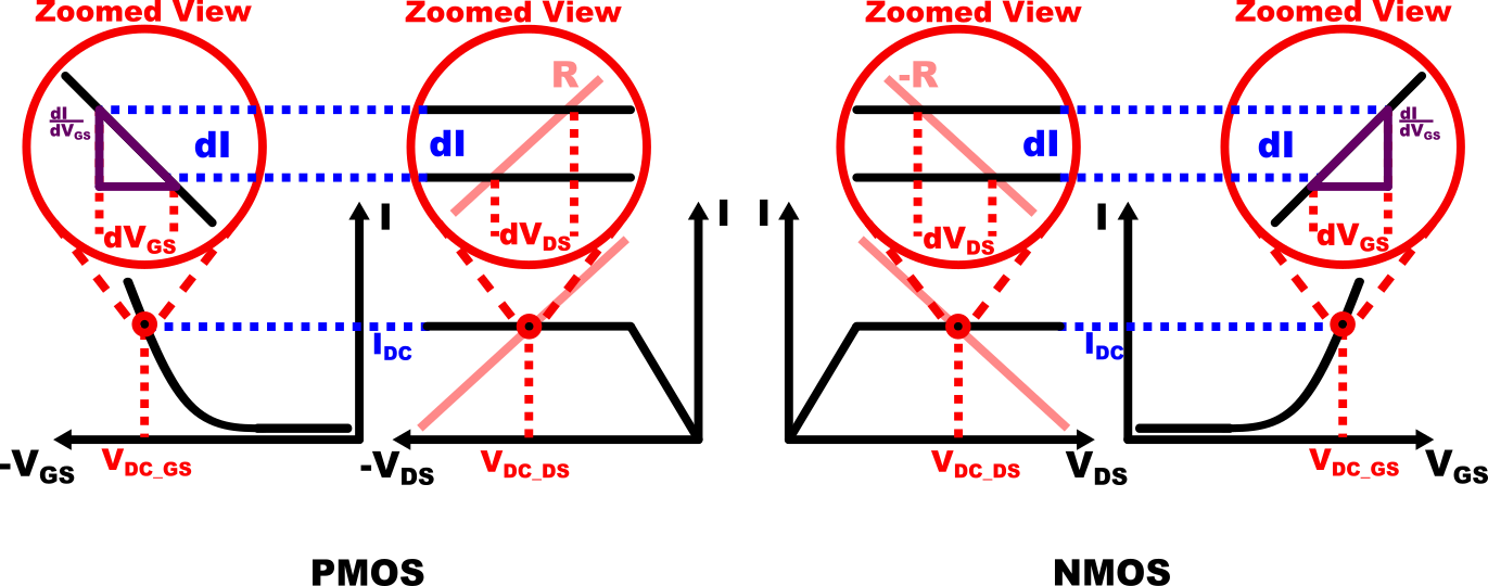
The assumption that we make in small signal analysis is that the voltage changes at the transistor are very small (duh!). By this assumption, once we decide the operating point of the transistor to a fixed value, it will not move far from the chosen operating point. This concept is shown in further detail in the Fig.5 below.

The main advantage of this approximation is that now we can obtain linear relationship between \( \Delta V_{GS}\) and \( \Delta I\) by calculating the constant slope at its opreating point i.e. \( \frac{d I}{dV_{GS}}\Bigr|_{\substack{V_{DC\_GS}}}\). We often call this value \(transconductance\) and write it as \(g_m\). Note that the value of the slope is negative for PMOS and positive for NMOS* i.e. \(g_{mP}=-g_{mN}\) .
* Positive or negative value of the slope depends on how we define the direction of current in the transistor. In this article, the direction of current in PMOS flows from Source to Drain while In NMOS it flows from Drain to Source. The author chose this definition because it represents how the current flows in real circuits.
Now that we understood the concept of small signal, let's apply these assumptions to our circuit from before. In both PMOS and NMOS, the \(V_{GS}\), \(I\) and \(V_{DS}\) can be expressed by \[ V_{DS}= V_{DC\_DS} + dV_{DS}\] \[ I= I_{DC} + dI \] \[ V_{GS}= V_{DC\_GS} + dV_{GS}\] where \( dV_{GS}\), \(dI\), and \(dV_{DS}\) show small deviations from the operating points \(V_{DC\_GS}\),\(I_{DC}\), and \(V_{DC\_DS}\). Interestingly enough, since \(V_{DC\_GS}\), \(I_{DC}\), and \(V_{DC\_DS}\) are constants, the changes now only depend on the small deviations \( dV_{GS}\), \( dI\), and \( dV_{DS}\) expressed by \[ \Delta V_{GS}= dV_{GS}\] \[ \Delta I= dI \] \[ \Delta V_{DS}= dV_{DS}\] now we can substitute the linear relationships between them in each NMOS and PMOS case
For NMOS:
- \(dV_{DS}=dI*-R \)
- \(dI= g_{mN}*dV_{GS} \space (g_{mN} > 0)\)
For PMOS:
- \(dV_{DS}=dI*R \)
- \(dI= g_{mP}*dV_{GS} \space (g_{mP} < 0)\)
This result shows that in either PMOS and NMOS, the voltage deviation from \(V_{DC\_GS}\) at the gate will be amplified to voltage deviation from \(V_{DC\_DS}\) at the drain. In addition, We can also confirm that in both cases, When \(dV_{GS}\) increases \(dV_{DS}\) will decrease with constant multiple of \(g_mR\). Obviously, from our assumptions, this result only holds for small deviation values.
The fact that voltage deviation is amplified in the circuit can be used to achieve signal amplification. We do this by inputting the signal as the deviation from \( V_{DC\_GS} \) which changes over time as shown below \[dV_{GS}(t)=v_{GS}(t) \leftrightarrow V_{GS}(t)= V_{DC\_GS} + v_{GS}(t)\] by doing this, now the deviation \(dI\) and \(dV_{DS}\) also changes over time as shown below \[dI(t)=i(t)=\pm g_mv_{GS}(t) \leftrightarrow I(t)= I_{DC} + i(t)\] \[dV_{DS}(t)=v_{DS}(t)=\mp i(t)R \leftrightarrow V_{DS}(t)= V_{DC\_DS} + v_{DS}(t)\] since the relationship between deviations are always \(linear \space regardless \space of \space time \), we can obtain the signal(voltage) gain \[ Signal Gain :=\frac{v_{DS}(t)}{v_{GS}(t)}= -g_mR \space \space \space (g_{m} > 0)\]
To summarize, Several key concepts that are introduced in this example are
- The circuit is assumed to operate at fixed operating points
- voltage deviations from the operating point of \(V_{GS}\) are amplified to voltage deviations from the operating point of \(V_{DS}\) by the circuit
- when the deviations are small enough, the amplification effect can be approximated as linear
- Signal amplification can be achieved by capitalizing on this amplification effect