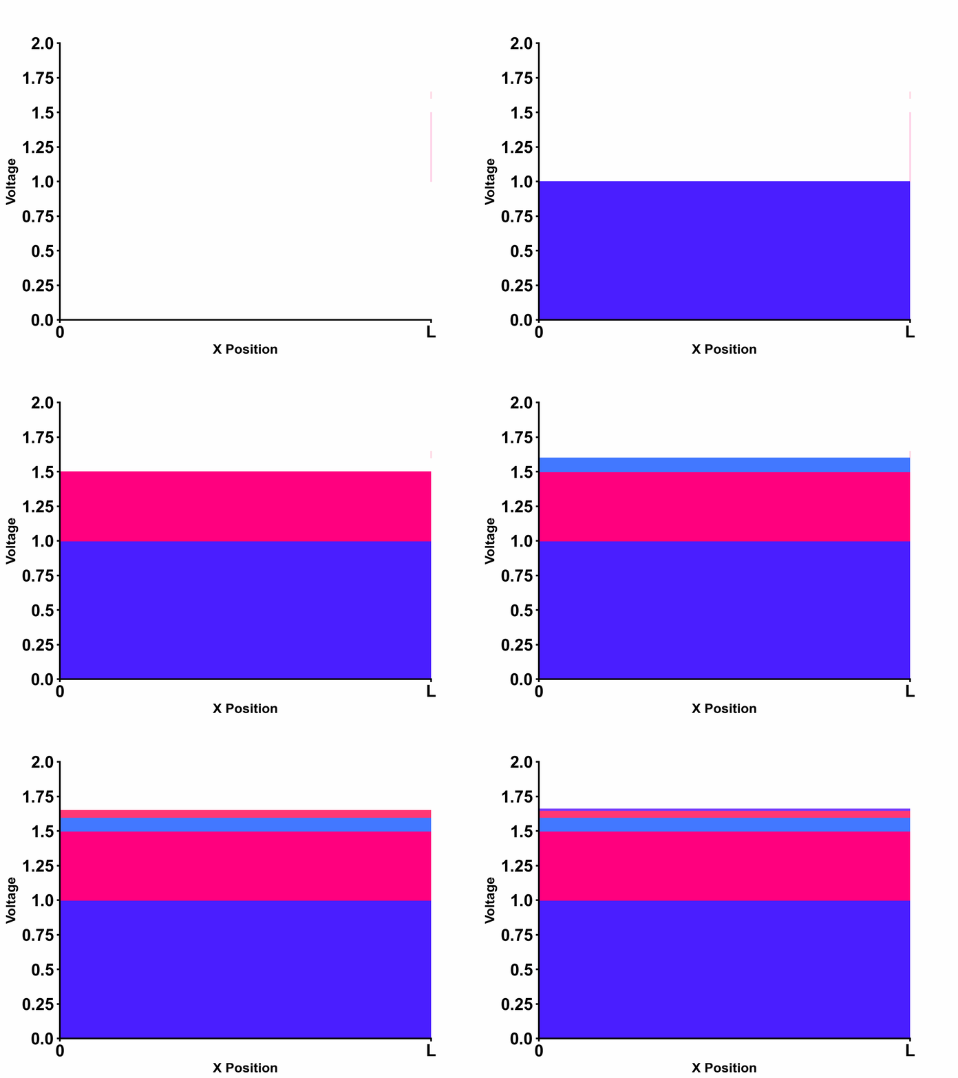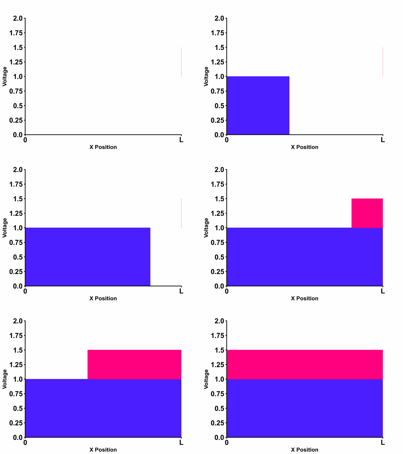
Figure 1 shows a terminated transmission line which is driven by a voltage source with non-zero source impedance. In this case, reflections happen at both source-side and load-side where each has its own reflection coefficient denoted by \(\Gamma_{SOURCE}\) and \(\Gamma_{LOAD}\).
To derive the solution for the example above, let us first calculate boundary conditions at source-side boundary (x=0) and load-side boundary (x=L):
- Boundary condition at \(x=0\): \[E_{(s)}-V_{(0,s)}=I_{(0,s)}Z_{s}\] \[ \Rightarrow (V_{+}+V_{-})=E_{(s)}-\frac{Z_{s}}{Z_{0}}V_{+}+\frac{Z_{s}}{Z_{0}}V_{-}\] \[ \Rightarrow V_{+}=\frac{Z_{0}}{Z_{s}+Z_{0}}E_{(s)}+\frac{Z_{s}-Z_{0}}{Z_{s}+Z_{0}}V_{-}\] \[ \Rightarrow V_{+}=\frac{Z_{0}}{Z_{s}+Z_{0}}E_{(s)}+\Gamma_{SOURCE}V_{-}\] From this we can see that wave travelling to the right side from x=0 boundary consists of voltage-divided input and reflected wave by \(\Gamma_{SOURCE}\) .
- Boundary condition at \(x=\ell\): \[V_{(\ell,s)}=I_{(\ell,s)}Z_{L}\] \[\Rightarrow V_{+}e^{-s\sqrt{LC}\ell}+V_{-}e^{s\sqrt{LC}\ell}=(V_{+}e^{-s\sqrt{LC}\ell}-V_{-}e^{s\sqrt{LC}\ell})\times \frac{Z_{L}}{Z_{0}}\] \[ \Rightarrow \frac{V_{-}}{V_{+}}=e^{-2s\sqrt{LC}\ell}\frac{Z_{L}-Z_{0}}{Z_{L}+Z_{0}}\] \[ \Rightarrow \frac{V_{-}}{V_{+}}=e^{-2s\sqrt{LC}\ell}\space\Gamma_{LOAD}\]
Substituting the obtained result to our original equation \[V_{(x,s)}=V_{+}e^{-s\sqrt{LC}x}+V_{-}e^{s\sqrt{LC}x}\] We get the final solution as follows: \[V_{(x,s)}=\frac{Z_{0}}{Z_{s}+Z_{0}}E_{(s)} \times \left[ \frac{1}{1-e^{-2s\sqrt{LC}\ell}\space\Gamma_{LOAD}\Gamma_{SOURCE}}e^{-s\sqrt{LC}x}+\frac{e^{-2s\sqrt{LC}\ell}\space\Gamma_{LOAD}}{1-e^{-2s\sqrt{LC}\ell}\space\Gamma_{LOAD}\Gamma_{SOURCE}}e^{s\sqrt{LC}x} \right] \] Interestingly, both incident wave terms and reflected wave terms represent geometrical sum with ratio \(e^{-2s\sqrt{LC}\ell}\space\Gamma_{LOAD}\Gamma_{SOURCE}\). This means that a new term appears periodically every \(2\sqrt{LC}\ell\) time delay with each new term's amplitude scaled according to \(\Gamma_{LOAD}\Gamma_{SOURCE}\). This implies that waves are bouncing at both the source-side and load-side boundaries as shown in Figure 2 below.

Much clearer and intuitive animation that describes this phenomenon is shown in Figure 3 below. In this animation, we can see the propagating waves and reflections at both source-side and load-side boundaries.

As further excercise, let us also consider what would happen when we match the source-side impedance to the transmission line characteristic impedance, that is considering the special case: \[ Z_{s}=Z_{0} \] In this case, there will be no reflections at source ( \(\Gamma_{SOURCE}=0 \) )and the solution will further simplify as follows: \[V_{(x,s)}=\frac{1}{2}E_{(s)} \times \left[ e^{-s\sqrt{LC}x}+e^{-2s\sqrt{LC}\ell}\space\Gamma_{LOAD} \space e^{s\sqrt{LC}x} \right] \] The step response of such source-matched transmission line is shown in the animation below:
